Wave Optics
Light as a wave
Huygens' Princinple
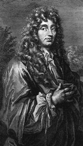
Christian Huygens [1629-1695]
1. Each point on a wave front is the source of a spherical wavelet that spreads out at the speed of the wave.
2. At a later time, the shape of the wave is the curve that is tangent to all the wavelets.
 Huygens' Sim


1. Each point on a wave front is the source of a spherical wavelet that spreads out at the speed of the wave.
2. At a later time, the shape of the wave is the curve that is tangent to all the wavelets.


1. Each point on a wave front is the source of a spherical wavelet that spreads out at the speed of the wave.
2. At a later time, the shape of the wave is the curve that is tangent to all the wavelets.
Index of Refraction
The index of refraction (or refractive index) of a material is a dimensionless parameter, $n$, used to describe how light moves in a particular medium.
$$n = \frac{c}{v} = \frac{\textrm{speed of light in vacuum}}{\textrm{speed of light in material}}$$The index of refraction of vacuum is $n = 1.000$ and is exactly 1.
| Medium | Index |
|---|---|
| Vacuum | 1 (exactly) |
| Air (0ºC, 1 atm) | 1.00029 |
| Water | 1.33 |
| Glass | 1.52 |
| Saphire | 1.77 |
| Diamond | 2.42 |
[*Note for labs: The index of refraction can change based on the wavelength of the light]
Index of Refraction
The velocity of the wave in a medium is given by: $v = \frac{c}{n}$.
From the previous visualization, we can see that the wavelength will also change.
Thus we can write $\lambda_n = \frac{\lambda}{n}$
What about the frequency?
Refraction

Refraction involves the bending of light at an interface between two medium with different indices of refraction.
We'll see that the following relation holds:
$$\frac{\sin \theta_1}{\sin \theta_2} = \frac{n_2}{n_1}$$Law of Refraction


Derive the law of refraction

Implications of refraction


Two light waves enter two different materials.
Upon exiting the material:

The waves are no longer in phase!
Yes, but by how much?
A single light beam is split into two equal beams, denoted A and B. Beam A travels through a medium with a higher index of refraction than the medium that beam B travels through. After both beams exit their media and are back into the air, how do their wavelengths compare?
- Beam A has a longer wavelength
- Beam B has a longer wavelength
- Both beams have the same wavelength
Based on the length of the materials, the indices of refraction, and the wavelength of the light in vacuum, we can determine the phase difference (actually the difference in number of wavelengths) between the two light waves.
$$N_2 - N_1 = \frac{L}{\lambda}(n_2 - n_1)$$Color
The color of light that we perceive is based on the frequency (or wavelength) of the light.

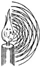
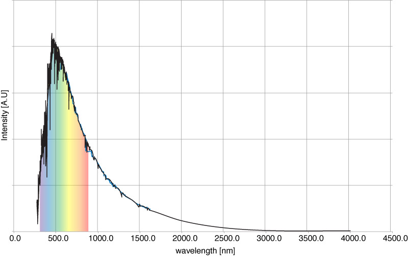
The light from the sun
Chromatic Dispersion

Here is a qualitative plot of the index of refraction for a hypothetical material as a function of the wavelength of the incident light.
Dispersion

The implications are that the angle of refraction is now dependent on the wavelength of the light because $n$ carries this dependence: $ n \rightarrow n(\lambda)$.
$$\sin \theta_1 n_1(\lambda) = \sin \theta_2 n_2(\lambda)$$
Diffraction
Diffraction

The spreading out of the waves after passing through the opening is called diffraction.
Diffraction is a general properties of all wave phenomenon. Water waves are particularly easy to see diffraction effects because the wavelengths are about as big as the obstacles which cause the diffraction.
Check out the Panama canal entrance: Link to Map

Wave interference

Two speakers?
Thomas Young
There were two competing theories about what exactly light was. Newton's experiments led him to postulate that light was a particle (he called them 'corpuscles'.)
While Huygens' and others had done work which seemed to show that light acted as a wave.
Thomas Young was an English Scientist. Around 1801 he did some experiments with light with the goal of demonstrating its wave-like nature.
The double slit experiment


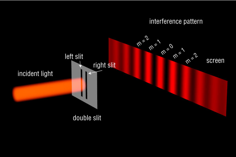

 $$\Delta L = d \sin \theta$$
When constructive:
$$d \sin \theta = m \lambda \mbox{ for } m = 0,1,2$$and for destructive:
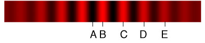
$$d \sin \theta = (m+1/2)\lambda \mbox{ for } m = 0,1,2$$A beam of monochromatic light with a wavelength of 660 nm is directed at a double slit. Consider the five locations labeled in the drawing, (the central maximum is labeled “B.”) Which one of these fringes is produced when the path difference is 1320 nm?
Light from a Laser has a wavelength of 633 nm. This is passed through two small slits spaced .4 mm apart. A viewing screen is 2.0 m behind the slits. What are the distances between the two m = 2 bright fringes and between the two m = 2 dark fringes, on the screen?
A laboratory experiment produces a double-slit interference pattern on a screen. If the screen is moved farther away from the slits, the fringes marked B and C will be:
- Closer together.
- In the same positions.
- Farther apart.
- Fuzzy and out of focus.
A double slit interference pattern is observed on a screen 1.0 m behind two slits spaced 0.30 mm apart. Ten bright fringes span a distance of 1.7 cm. What is the wavelength of the light?

Of course, as scientists, we would rather have our data in a more useable form. To this end, we can convert our 'screen' images of dark and light spots to an intensity plot. This lets us put units, like $W/m^2$ for intensity as a function of distance, and use functions to desribe the plot.
The same information is present -- it's just easier to work with.
A laboratory experiment produces a double-slit interference pattern on a screen using red light. If green light is used, with everything else the same, the bright fringes will be:
- Closer together.
- In the same positions.
- Farther apart.
- Fuzzy and out of focus.
Waves and Reflections
We saw what happened when a wave on a string reflected off a boundary.
Boundary is not perfect
Here we have a wave on a rope traveling towards a partially reflecting boundary. The 'boundary' is really a connection between a low density and high density section of rope.
Boundary is not perfect
Likewise, if the wave travels from a higher density region to a lower density region, most of the wave's energy will be transmitted, while some will be reflected.
Again, the lower density section of rope will have a higher wave speed than the high density region. This time, there is no amplitude inversion. vid
Phase change due to reflection
Since the index of refraction of a material is somewhat analogous to the density of a string, as far as waves go, (they both are parameters that affect the speed of the waves), we would expect a similar phenomena with light as it reflects from boundaries.

Depending on if the light is reflecting off a higher index or a lower index, we will obtain the following phase shifts for the reflected waves.
| Reflection | Phase shift |
|---|---|
| Reflects off a lower index | 0 |
| Reflects off a higher index | 0.5 |


Blue laser light is traveling through a sandwich of materials as shown. At each interface, some light will be reflected. Comparing the original incident ray with the final reflected ray, what is the phase shifts due to reflection?
- 0 rad
- $\pi/2 $ rad
- $\pi$ rad
- $3 \pi / 2$ rad
- $2 \pi $ rad
Phase Shift Sources
We now have 3 sources of phase shifts for a light wave:
- Reflection: depending on the $n$ of the two media, the reflected wave may or may not be phase shifted
- Path Length: The analysis of the double slit showed that path length difference can also lead to a phase shift.
- Index of Refraction: Light traveling through media with different $n$ can undergo a phase shift.
Thin Film Interference

Thin Film Interference

① The original incident ray is both reflected and transmitted at the first boundary. This reflection becomes $r_1$. The transmitted wave goes until the next boundary, ②, where it is also transmitted and reflected. The reflected ray proceeds back through material 2, and it then transmitted through the boundary at ③. This last transmitted ray is $r_2$.
By figuring out all the phase shifts along the way, we can tell if rays $r_1$ and $r_2$ will be in phase or out of phase. That is, will they constructively interfere or destructively interfere?
Constructive interference

In this situation, we have $n_1 < n_2>n_3$.
Since at the interface ① the ray is reflecting off a large $n$, the reflected ray $r_1$ will have a phase shift of $\lambda/2$.
$r_2$ will have a path length difference compared to $r_1$ of 2L. Thus to get constructive interference between $r_1$ and $r_2$, we need
$$2L = \left(\frac{\textrm{odd number}}{2}\right) \lambda_{n_2} = \left(m+\frac{1}{2}\right)\frac{\lambda}{n_2} \;\;\textrm{for } m = 0,1,2, \ldots$$
Destructive Interference
If we where looking to have destructive interference between the two reflected rays, we would need:
$$2L = \textrm{integer} \times \lambda$$.Thus, with the same substitutions, we can arrive at:
$$2L = \left( \textrm{integer} \right) \lambda_{n_2} = m \frac{\lambda}{n_2}\;\;\textrm{for } m = 0,1,2, \ldots$$What is the thinnest film of MgF2 (n = 1.38) on glass that produces a strong reflection for light with a wavelength of 600nm.
Two 15-cm long flat glass plates are separated by a 10 $\mu$m thick spacer at one end, leaving a thin wedge of air between the plates. A monochromatic light ($\lambda = 589$nm) from above illuminates the plates. Alternating bright and dark fringes are observed. What is the spacing between two bright fringes.

If the film is much smaller than the wavelength of the light passing through, (i.e $t < .1 \lambda$), then we can ignore the path length created by the film and only concern our analysis with the reflections of the light at the boundaries.

Since the criteria for constructive and destructive interference depends on wavelength, light of different colors will respond differently to a thin film, like a soap bubble or oil slick. Some colors will experience constructive interference, while others will have destructive interference after the two reflections.
Interferometer
We’ve seen that the amount of light visible is very sensitive to the path difference between two rays. This means we can make a device to measure very small distances.

The smallest length we can measure using this device will be given by the wavelength of the light used.

Interferometer

We know the path length difference is: $$\Delta r = 2 L_2 - 2 L_1$$ When $\Delta r$ is equal to a whole number of wavelengths, ie: $\Delta r = m\lambda$, then the interference between the two paths will be perfectly constructive. Any change in the amplitude of the final, detected light, implies a change in either the wavelength of the light during one arm of travel, or a change in the length of one arm.
Uses of interferometry:
- Disproved the Luminiferous Aether
- Surface topography of samples.
- Measured Newton’s Gravitational Constant, G.
- Maybe gravitational waves??? (lookup LIGO - http://www.ligo.caltech.edu/)
The diffraction of light
Our use of the ray model relied on the assumption that the light rays didn't interact with objects that had features in the same length scale as the wavelength of the light.
Clearly, this limits the range of topics we can discuss, and it limits the depth of phenomena we can understand.
Let’s go back to this: A monochromatic light source passing through a small slit.
The wavelength of this light is roughly the same size as the slit through which it is passing.
Single Slit
The set up is the same as the double slit, except there is only one slit.
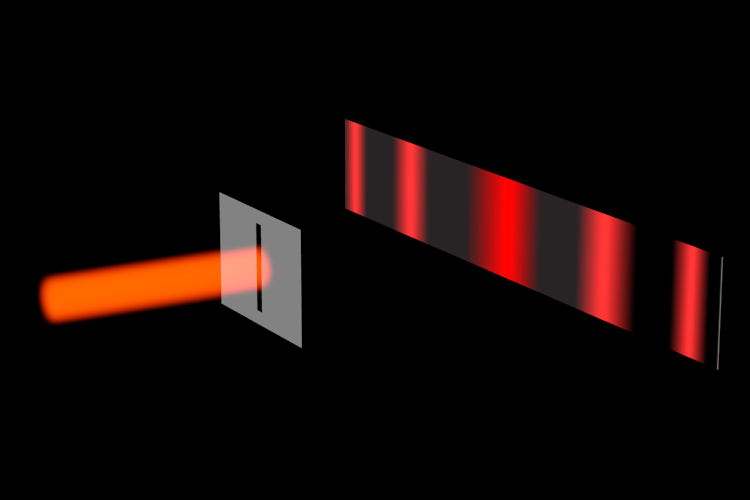
Again, we see a diffraction pattern emerge on the screen. This one is a bit different however.
Huygens-like analysis of a single slit

Ⓐ The wavelets from each point on the initial wavefront overlap and create an interference pattern
Ⓑ These all travel the same distance and create the central maximum
Ⓒ These travel different distances and create the fringes.

The path length difference between wavelet 1 and 2 is:
$$\Delta r_{12} = \frac{a}{2} \sin \theta$$Which is another way of saying that wavelet 2 travels $\Delta r$ more to get the screen at the angle $\theta$.
If $\Delta r_{12} = \lambda/2$, then so are all the other ∆r values, and the interference at the screen will be destructive, meaning there will be a dark spot there. The locations of the dark spots are then: $$\frac{a}{2}\sin \theta = \frac{\lambda}{2}$$ or, $$a \sin \theta = \lambda$$
The other minimums can be figured out in a similar way. We get the following for the angular locations of the dark regions. $$a \sin \theta = m \lambda$$
The width of the central maximum is easily figured by looking at the distance between the first minimums. $$ y = \frac{m \lambda L}{a}$$ thus: $$w = \frac{1 \lambda L}{a} + \frac{1 \lambda L}{a} = \frac{2 \lambda L}{a}$$

Light of wavelength $\lambda$ illuminates a single slit so that the width of the central diffraction maxima is $l$. The slit width is then decreased to $a/2$. What is the width of the central diffraction maxima?
- $l/2$
- $2l$
- $l/4$
- $4l$
- $l$
Now let's keep the same slit width, but change the wavelength. What happens to the width of the central maximum if you decrease the wavelength of the incident light?
- Increases
- Decreases
- Stays the same
Multiple Slits
What happens when we increase the number of slits?

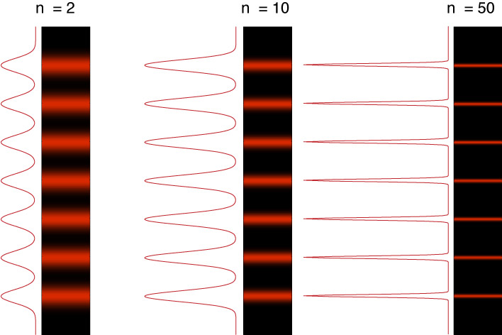
This system is called a diffraction grating. We can think of it as a multi-slit device.

We can increase the number of slits per inch. Here's 5 slits and a sample of what the diffraction pattern would look like.

Using the same analysis as before, we can find the locations on the screen where the path length difference leads to constructive interference.
$$ \Delta r = d \sin \theta = m \lambda$$ $$ (\mbox{for } m = 1,2,3)$$Again, note that this value is dependent on the wavelength.
The quality (sharpness and intensity) of the diffraction pattern is determined by the number of slits in the grating. As the number of slits, n, increases, the width of the fringes decreases, but their intensity increases.
Different wavelengths will have maximums at different positions along the screen.

Awesome Tool: The spectrometer
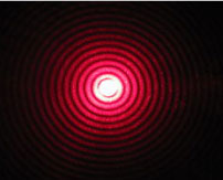
Circular Aperture Diffraction

Monochromatic light which passes through a very small circular aperture will create a circular diffraction pattern like this.
The location of the first minimum can be found by: $$\theta_1 = 1.22\frac{ \lambda}{D}$$
The lens as an aperture

A lens can be considered a type of aperture. There will be diffraction of the light waves as it passes through.
Two distant stars

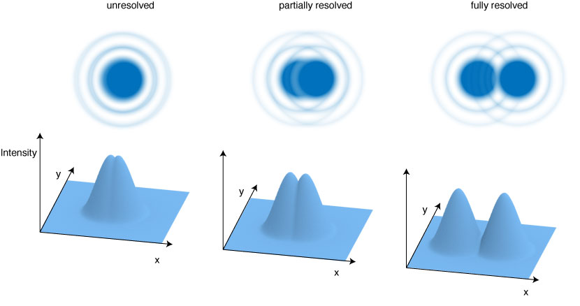
Rayleigh's Criterion
Two point sources can only be resolved if their angular separation, $\alpha$ is greater than:
$$\theta_R = \sin^{-1}\frac{1.22 \lambda}{D} \approx \frac{1.22 \lambda}{D}$$Two lightbulbs are 1.0 m apart. From what distance can these lightbulbs be resolved by a small telescope with a 4.0 cm diameter objective lens. Assume that the lens is diffraction limited and $\lambda$ = 600nm.
Resolving Power: In general, we can say the resolution for any optical instrument is limited by the wavelengths of the light used.
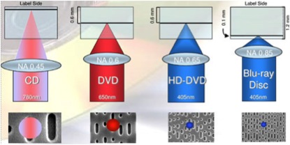
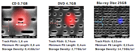
Guess what color the light from a Blu-ray player laser is? Why?