What are we even measuring here?
Analog In
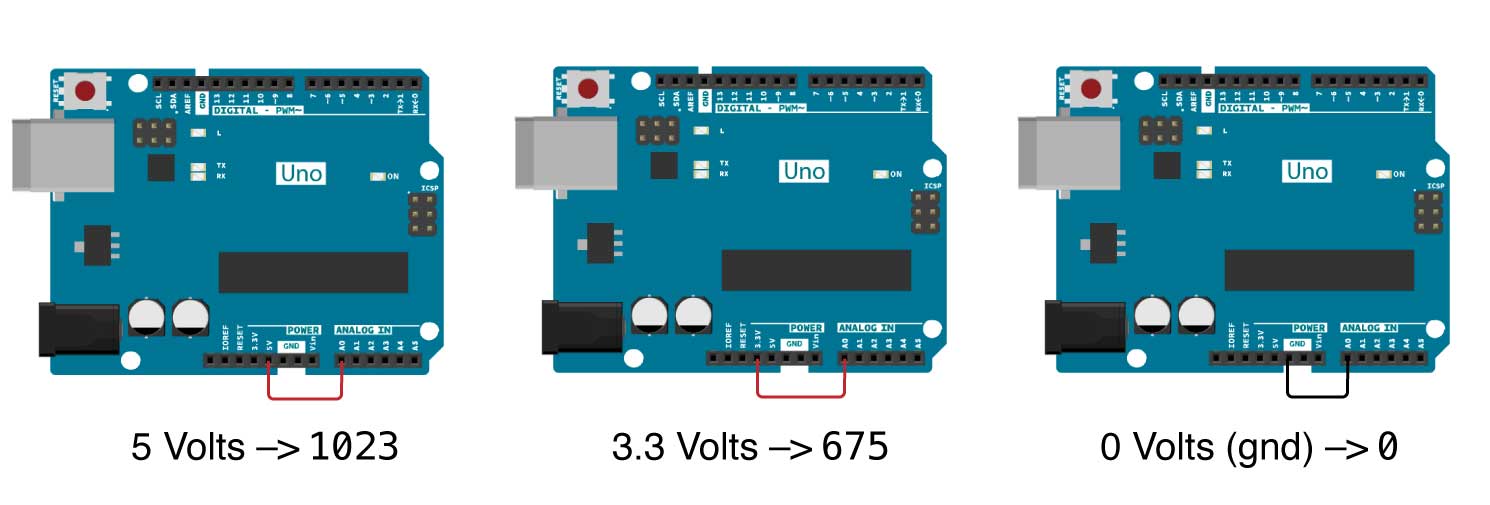
Using the Analog In ports on the Arduino, we can measure a voltage. The Arduino will report this value, not in volts, but in a quantity that is set by the resolution of the device. In this case, our boards have a 10-bit analog to digital converter, which means that it will map the range of voltages (0 - 5V) to a range of $2^{10} = 1024$ values.
| Input | Output |
|---|---|
| 0.0 V | 0 |
| 2.5 V | 512 |
| 5.0 V | 1023 |
This is simple enough to check for yourself. Just load up the Example sketch AnalogReadSerial and try connecting the pins labeled 5V, 3.3V, and Gnd to the A0 pin, one at a time, and watching the Serial Monitor to see.
3 simple voltage measurements
As an equation, this would look like: $$ \texttt{Serial A0} \times \frac{5 \; \textrm{V}}{\texttt{1023}} = \textrm{Measured Voltage}$$
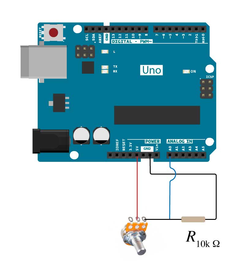
So now that we can measure voltage, the next thing to do is to use Voltage as a proxy measurement for something else, like a Resistance. This can be accomplished by using a simple voltage divider circuit.

A voltage divider.
Here is the voltage divider. Since the voltage drop is proportional to the resistance between each two measurement points, we can compare an unknown resistor value to a known resistor by measuring the voltage drop across the known resistor.
The equation, easily derivable, is $$ V_{\mathrm {out} }={\frac {R_{ref}}{R_{unknown}+R_{ref}}}\cdot V_{\mathrm {in} }$$

A simple test of your circuit.
To make sure you have built a voltage divider correctly, try the following. Use 2 x 10k Ohm resistors. The look like this: and will have bands colored Brown, Black, Black, Red, Brown.
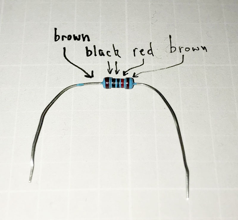
This is a 10k resistor
If you've set up your voltage divider correctly, you should see measure about 512 which corresponds to 2.5 V, which makes sense if:
$$ V_{\mathrm {out} }={\frac {10 k}{10 k+10k} \times 5 \; \textrm{V} = 2.5 \; \textrm{V}}$$
To test your understanding, grab another resistor from your packet. Look for the one with 2 Red bands followed by 2 Black Bands. Put that in for you unknown resistor in your circuit. You should measure an input in A0 of about 1001 or 1002. This is about 4.89 Volts since: $$ \texttt{1001} \times \frac{5.0 \; \textrm{V}}{\texttt{1023}} = 4.89 \; \textrm{V}$$ Now you can use that value as the $V_\textrm{out}$ in the voltage divider equation and obtain your resistance of the 'unknown' resistor. If you did your math and measurements right, you should get a value for the unknown resistor that is approximately the same as the year that the city of Megalopolis was burned down by the Spartan King Cleomenes III.
Now, you should be able to take any unknown resistor, and plop it in your voltage divider, and measure the resistance of it.
Try putting your potentiometer in the Unknown Resistor section.
One further thing you can try is putting a Variable Resistor, otherwise known as potentiometer, or pot. This device lets you change the resistance by turning the knob. The one in your kit ranges from 0 to 10k.