Lab 3: Make a Heater and Measure Temperature
The goal: Make a simple heater and use the thermistor to measure its output.
Overview:
Any amount of current passing through a resistor will create some heat. This can be expressed analytically by the power dissipated, which is given by \begin{equation} P = I V = I^2 R \end{equation} We can use a regular resistor and supply it with a current from the Arduino to make a very rudimentary heater element. (It's not much different than a toaster, except the currents are much smaller so we don't have worry about burning our toast.) We've already built a temperature measurement device using the thermistor. This project joins the two into a heater/thermometer system.
Warmup exercise:
Make sure you can use the PWM output (i.e. digital out) to make the LED change brightness. Connect the LED in series to the arduino with a resistor (300 Ω is fine). Here's some code and circuit diagram to start with. We will make the potentiometer control unit next class, Oct 10th. It will be able to do this: Brightness Control
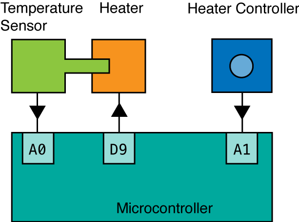
The block diagram for the experiment
We can consider an overview of the entire project as shown here. We have 4 primary elements:
- Microcontroller (Arduino)
- The Heater (a resistor)
- The Temperature Sensor (Thermistor)
- The Heater Control (Potentiometer)
The previous labs and demos have built up each component of the project. Now the idea is the put them together into one application: A controllable heater with a temperature sensor.
Detailed Instructions
- Use the voltage divider method to build the temperature measurement component of the setup. This is essentially the same thermistor based measurement setup you already did. Measure this value on an
Analog Inpin. - Set up the potentiometer to send its 'value' to another
Analog Inpin. The potentiometer is really just a voltage divider built into a single component. - Connect a 220 Ω resistor between a
Digital Out/PWMpin and ground. This is the heater. - Important!! Make sure the Rheater is in physical contact with the thermistor, like shown in the picture below. If there is a gap between the resistor and the thermistor, then there will be less heat transferred.
- Use the input from the potentiometer to control the duty cycle of the output to the Rheater (just like we did with the LED brightness controller from last week.) All the code necessary for this project has been seen in the previous weeks of the course. It shouldn't require any thing new, but perhaps just a little rearranging.
- Output the time, potentiometer value, and thermistor measurements to the serial log. It should be comma separated and each line would then have three distinct numerical values: time, pot value, therm value. The video below shoes the disired output correlated with the action of the device.
- Set your
delay()pararemeter to 200 milliseconds, so it records 5 data points per second. - Make a plot showing that your heater works. (no, you can't use excel)
- Adopt the Colab example on data and fitting to show that your measured temperature change fits to an expected function for $T(t)$ as predicted by basic physics. Explain.
Please prepare your report as follows.
- Short introduction in your own words describing the experiment.
- Full detailed electrical schematic diagram, not hand-drawn. (i.e. not a block diagram like above, but a real schematic with all the parts labeled and wires etc.)
- Photograph of your set up.
- Make sure your photograph correlates with the circuit diagram you make, and make sure they are clear enough to see that various parts.
- Your Arduino code (or link) - the actual copied code please (not a screenshot of your sketch).
- Links to any Colab notebooks you made for data analysis. Just make sure you have the sharing attributes set. If it says 'no access' when I click it, then that's where I stop.
- Your data. Please do not include 20 pages of data. Link to a file online somewhere. (google drive, github, etc)
- The plot showing that your heater is being controlled by the potentiometer and that the temperature of the resistor is being measured as expected. This is where you prove to me that your device works!
- The plot your temperature change makes sense physically (i.e. the fit)
- Any references or citations can be included as end notes.
- Make the report into a single document delivered as a pdf, not a hodgepodge collection of images, words, etc. Here's an example: Example Report pdf Name your pdf as:
LastName_FirstName-Lab3.pdf - Submit via the Blackboard Lab 3 submission page by 4pm Oct 28.
Other notes:
Our heater is really a very bad heater. The output current we are using from the Arduino is not intended to be used as a heater source current, so you must be sure to not put too small of a resistor in this part. I suggest 220 Ω for your heater. When you change the output of the PWM pin, you aren't changing the current, but the duty cycle. So that means it's only delivering the current for some fraction of the time, not changing the value of the current outputted.
The physical contact between the resistor and the thermistor is crucial. Arrange your board so that the two are close and can be held together with the tension in their metal legs.
Put the potentiometer far away, so that when you adjust it, you don't accidentally disrupt the thermistor/heater contact.
I put an LED on another PWM output with a brightness controlled by the heater output. Not necessary, but might be helpful for debugging.
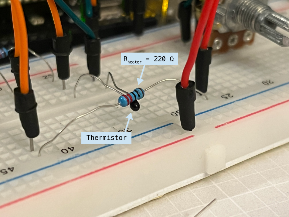
The Heater and the Thermistor are in physical contact.
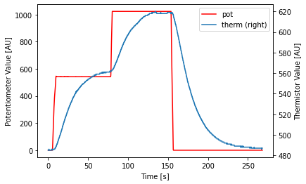
Example plot showing the temperature being controlled by the potentiometer.
Here is an example plot. The Potentiometer was set to about 50% of its maximum value after a few seconds. After the temperature stabalized, the potentiometer was increased to 100%, at around 80 seconds. After about 150 seconds, the potentiometer was reduced to a minimum, and the temperature slowly returned to the initial reading.
Example video
The video below shows the completed device and the serial monitor output as I change the pot to half its max value and then back to zero over the course of about a minute.